
Overview
- This page provides a practical deployment template for NVMe/TCP Boot from SAN on Dell PowerEdge servers
- The overall workflow is:
- gather required parameters
- prepare the boot namespace on the storage side
- configure BIOS/iDRAC boot settings
- install the OS to the remote NVMe device
- apply post-install tuning
Goal
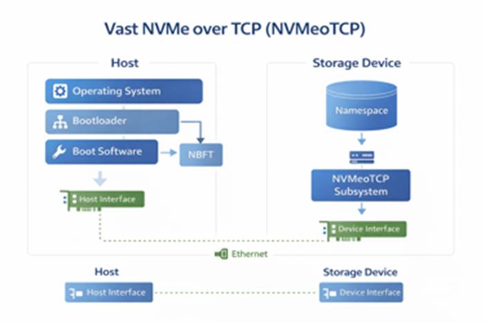
- Boot the operating system directly from a remote NVMe/TCP namespace over Ethernet.
- Avoid dependency on local boot disks.
- Keep boot images centralized and easier to replace or recover.
Important note: Compatibility of server models for supporting NVMe Boot from SAN should be verified directly with Dell.
2) Recommended High-Level Flow
- Preparation
- Collect the host NQN
- Collect the host IP addresses for each boot NIC / SAN path
- Collect the target subsystem NQN
- Collect the discovery IPs or direct target IPs
- Collect the required ports
- Collect VLAN details, subnet mask, and gateway information if relevant
- Storage-side setup
- Create the boot namespace / volume on the storage platform
- Map the namespace to the host NQN
- Confirm the target is exposed on the expected IPs and ports
- Server-side setup
- Enable NVMe-oF boot in BIOS/iDRAC
- Define one subsystem per SAN path
- Apply the correct target addressing method
- OS install
- Boot the installer ISO
- Verify the remote NVMe device is visible
- Install the OS onto the remote NVMe disk
3 )Information to Collect Before Starting
3.1) Host-side information
- NVMe-oF Host NQN
- NVMe-oF Host ID
3.2) Target-side information
- NVMe-oF subsystem NQN
- Discovery controller IPs, if using discovery-based configuration
- Direct target / I/O controller IPs, if using static target entries
- NVMe/TCP service port
- Namespace mapping details
4) Steps to Customize for VAST
Please note that a few reboots will be required in order to expose and configure all the BIOS options listed below.
4.1) Configure NVME Settings
- Log in to iDRAC.
- Go to:
- Configuration > BIOS Settings > NVMe Settings
- Set BIOS NVMe Driver to All Drives
- Expect the values to remain pending until the system reboots.
4.2) Enable NVME-oF
- Log in to iDRAC.
- Go to:
- Configuration > BIOS Settings > Network Settings > NVMe-oF
- Set to Enabled
- Expect the values to remain pending until the system reboots.
4.3) Configure Network Settings
- Log in to iDRAC.
- Go to:
- Configuration > BIOS Settings > Network Settings >NVMe-oF SubSystem Settings
- Set NVMe-oF SubSystem1 > Enabled
- Expect the values to remain pending until the system reboots.
4.4) Collect host information from iDRAC
- Log in to iDRAC.
- Go to:
- Configuration > BIOS Settings > Network Settings
- Record the NVMe-oF Host NQN.
- Record any NIC-specific information that will be used for the boot paths.

4.5) Define the NVMe-oF boot subsystems
- Configure one boot subsystem entry per SAN path.
- For each subsystem entry, define:
- interface / NIC port
- protocol
- VLAN settings if needed
- host IP address and subnet mask
- target subsystem NQN if using direct target mode
- target address
- target port
Two common configuration models
- Discovery controller method
- leave the subsystem NQN empty
- point BIOS to the discovery controller IP
- use the discovery service port
- Direct target method
- enter the subsystem NQN explicitly
- point BIOS directly to the target IP
- use the target service port

4.6) Prepare the boot namespace on the storage side
- Create the namespace / volume that will hold the operating system.
- Map it to the host using the host NQN collected from iDRAC.
- Confirm that the namespace is presented through the expected NVMe/TCP target IPs and ports.
4.7) Collect target-side information from VAST
- Gather the target-side values needed by BIOS/iDRAC:
- subsystem NQN

- discovery IPs or direct target IPs

- NVMe/TCP port – 4420
- namespace-to-host mapping

4.8) Reboot and boot the OS installer
- Apply the BIOS changes.
- Reboot the host
- Boot from OS installer ISO.
- Confirm that the remote NVMe/TCP disk is visible as an install target.
- Install the OS onto the remote NVMe device.
If the boot disk is not visible
Use the installer shell and verify:
- NVMe subsystem visibility
- NBFT handoff – the process where the system firmware, usually BIOS/UEFI, passes NVMe Boot Firmware Table information to the operating system during boot.
- IP addressing
- target reachability
nvme list-subsys
nvme nbft show
ip addr
ping <target-ip>
These checks help confirm that BIOS handed the boot configuration to the OS correctly and that the target is reachable.
Choosing Device During Install


During Install

During reboot:

5) Post-Install Validation
Confirm the system is really booting from the remote NVMe device
- After the OS installation completes, verify:
- the target NVMe namespace is present
- / and boot-related filesystems reside on the expected NVMe device
[root@localhost ~]# nvme list
Node                  Generic               SN                   Model                                    Namespace  Usage                      Format           FW Rev
--------------------- --------------------- -------------------- ---------------------------------------- ---------- -------------------------- ---------------- --------
/dev/nvme0n1          /dev/ng0n1            VST0000000e          VASTData                                 0x1          6.54  GB /   2.00  TB    512   B +  0 B   5.5.0

[root@localhost ~]# nvme list-subsys
nvme-subsys0 - NQN=nqn.2024-08.com.vastdata:4ebc5121-259c-53b4-99b4-4e4a1a3d9f03:default:blockbfs
               hostnqn=nqn.1988-11.com.dell:PowerEdge.R760.8DH3QH4
\
 +- nvme0 tcp traddr=172.21.73.1,trsvcid=4420,host_traddr=172.21.222.214,src_addr=172.21.222.214 live


 [root@localhost ~]# df -h
Filesystem           Size  Used Avail Use% Mounted on
devtmpfs             4.0M     0  4.0M   0% /dev
tmpfs                126G     0  126G   0% /dev/shm
tmpfs                 51G  9.9M   51G   1% /run
efivarfs             304K  192K  108K  64% /sys/firmware/efi/efivars
/dev/mapper/rl-root   70G  5.9G   65G   9% /
/dev/mapper/rl-home  1.8T   13G  1.8T   1% /home
/dev/nvme0n1p2       960M  336M  625M  35% /boot
/dev/nvme0n1p1       599M  7.1M  592M   2% /boot/efi
tmpfs                 26G  4.0K   26G   1% /run/user/0
[root@localhost ~]# nvme nbft show
/sys/firmware/acpi/tables/NBFT:
NBFT Subsystems:
Idx|NQN |Trsp|Address |SvcId|HFIs
—+——————————————————————————+—-+———–+—–+—-
1 |nqn.2024-08.com.vastdata:4ebc5121-259c-53b4-99b4-4e4a1a3d9f03:default:blockbfs|tcp |172.21.73.1|4420 |1
NBFT HFIs:
Idx|Trsp|PCI Addr |MAC Addr |DHCP|IP Addr |Mask|Gateway |DNS
—+—-+———-+—————–+—-+————–+—-+——–+——–
1 |tcp |0:b5:0.0 |b4:5c:b5:c1:c3:94|yes |172.21.222.214|16 |0.0.0.0 |0.0.0.0
NBFT entry detected on the host:
- single VAST NVMe/TCP subsystem is defined in the table
- Target endpoint: 172.21.73.1:4420
- The target is associated with host fabric interface 1
- Host fabric interface 1 maps to NIC 0:b5:0.0
- NIC MAC address: b4:5c:b5:c1:c3:94
- Host IP address: 172.21.222.214/16 obtained via DHCP
- Both host and target reside in the same /16 network
- No gateway is required, matching the 0.0.0.0 gateway value
To complete the NVMe configuration setup, please refer to:
https://kb.vastdata.com/docs/persisting-nvme-of-over-tcp-across-reboots
Leave a Reply